Difference between revisions of "Lockpicking contest system"
| (5 intermediate revisions by one user not shown) | |||
| Line 1: | Line 1: | ||
== Rumble Challenge Lock Picking Contest System and Drinking Game== | == Rumble Challenge Lock Picking Contest System and Drinking Game== | ||
| + | Here at the Fraternal Order Of Lock Sport we take both our sport and our drinking very seriously. For DerbyCon this year we decided we wanted to encourage both as much as possible, so with that in mind we built the Rumble Challenge. It's a lock picking game where 6 people compete head-to-head for the best time each round. Each lock stand has a sensor which allows the microcontroller (ATMega328) to detect and score the players times. Each lock stand has a rumble motor attached which randomly goes off. Why? It's hilarious to see everyone jump when they go off (they are loud), it also throws off the feel of whats happening with the lock. | ||
| − | + | When the drinking-mode is activated, each time a lock is opened an air-pump triggers which pressurizes a carboy containing the precious liquid to fill each players shot glass. The game stops, each player still in the game gets a shot bonus, then the GO button is pressed to continue. Players who have already opened their locks still get a shot, but no bonus points. Scoring is setup so that getting your lock open first is great, but getting all 6 shot bonuses can potentially put you in first place too. | |
| − | + | ||
| − | + | ||
| − | + | ||
== Hardware == | == Hardware == | ||
| − | + | First I mocked-up a vibration motor to a lock stand to see if it would be enough to actually interfere with picking. The first tests were very promising, so I went ahead and geared the project up to full speed. | |
[[Image:IMG_0858.JPG|none|thumb|300px|Vibration motor mockup]] | [[Image:IMG_0858.JPG|none|thumb|300px|Vibration motor mockup]] | ||
| Line 37: | Line 35: | ||
== Electronics == | == Electronics == | ||
| − | I used an Arduino to prototype the circuit. It's so simple to get an ATMega running on perfboard that I don't waste real Arduino's in my final circuits, just put a socket in there and swap chips when you are done with the code. It transmits lock open-events to a receiver (connected to a PC connected to a projector) as well as dispenses shots in drinking-game-mode :-). The controller has an LCD display so it could operate stand-alone, however I'm more interested in using some cheap RF boards to transmit events to the projector system. I was able to get the code written while I was waiting for parts to ship from SparkFun and Jameco. I' | + | I used an Arduino to prototype the circuit. It's so simple to get an ATMega running on perfboard that I don't waste real Arduino's in my final circuits, just put a socket in there and swap chips when you are done with the code. It transmits lock open-events to a receiver (connected to a PC connected to a projector) as well as dispenses shots in drinking-game-mode :-). The controller has an LCD display so it could operate stand-alone, however I'm more interested in using some cheap RF boards to transmit events to the projector system. I was able to get the code written while I was waiting for parts to ship from SparkFun and Jameco. While the RF system worked great at first, it seems that the motors were causing some occaisonal interference so for the final design I added an FTDI header and used a SparkFun FTDI breakout board for USB connectivity. It's a simple code change to switch from RF to Serial output for communication with the Processing app. For the RF receiver I just used an Arduino+SparkFun proto-shield and receiver board, I didn't have time to build a permanent circuit which was just as well. |
| − | + | This schematic is merely a suggestion, the only reason I used various pins was because they were free. There are probably a lot of ways to do this better, this is just the way I built it. Some gotchas, the Arduino pins have to be translated to ATMega328 pins, that's usually documented below. The air-pump should run at 1.5V but I'm running it at 5V. You will need a large heat-sink on your power regulator if you do this. I tested the motor before going with this setup, it draws between 300mA and 400mA at 5V which is well within the regulators 1A max. Also, you may enjoy adding things like a reset switch to the microcontroller. | |
{| | {| | ||
| + | | [[Image:Rumble_challenge_schematic.jpg|none|thumb|250px|Schematic]] | ||
| [[Image:IMG_0889.JPG|none|thumb|300px|Top: prototype, Bottom: final circuit]] | | [[Image:IMG_0889.JPG|none|thumb|300px|Top: prototype, Bottom: final circuit]] | ||
| [[Image:IMG_0900.JPG|none|thumb|300px|Left: lock stand, Right: electronics in enclosure]] | | [[Image:IMG_0900.JPG|none|thumb|300px|Left: lock stand, Right: electronics in enclosure]] | ||
|} | |} | ||
| + | |||
| + | == Debugging == | ||
| + | One major problem I ran into with this system is noise from the electric motors causing spurious CPU corruption and lockups. This was a head scratcher for a long time but the answer turned out to be simple in the end. First I isolated the motors to have their own power supply independent from the CPU power supply. This didn't do much, but then I realized I had connected the grounds between the CPU and motor power. I cut these apart on the PCB so the grounds were completely isolated. This helped a lot however it would still lock up often enough to cause major headaches. Also running the air pump/shot dispenser would still lock up the CPU about 80% of the time. Finally a friend suggested putting capacitors on the motors. There are multiple ways to do this, I added two 105 caps to each motor, one cap going from each power lead to the motor case. I also did this on the air pump motor along with a cap across the power leads (in parallel to the motor) since this motor was the worst offender. This solved all of the corruption and lockup problems, the system is 100% reliable now. | ||
| + | |||
| + | [[Image:Rumble_challenge_motor_caps01.jpg|none|thumb|200px|Motor caps installed]] | ||
| + | |||
| + | Also, for drinking mode, I need to do some work on the "liquid delivery system" by adding fish-tank ball-values on each output tube. Getting even flow of liquid to each shot glass is difficult with the tubing spralled out across a table, differences in tube length, and differences in height. The biggest problem is over-filling shot glasses and having to stop delivery to stations which are missing a player for a round. | ||
== Visualisation == | == Visualisation == | ||
| Line 53: | Line 59: | ||
== Code == | == Code == | ||
| − | + | Email me if you are interested in code (dosman [at] bloominglabs [dot] org). | |
| − | + | ||
== Action Shots == | == Action Shots == | ||
| − | The first run of the game was during DerbyCon at LVL1's party. We setup the system in full drinking-game-mode with Malibu Rum as the potion of choice. Many thanks for the awesome folks at LVL1 for letting us run the game at their space (hotel rules prohibited drinking in the lock picking village at DerbyCon). | + | The first run of the game was during DerbyCon 2011 at LVL1's party. We setup the system in full drinking-game-mode with Malibu Rum as the potion of choice. Many thanks for the awesome folks at LVL1 for letting us run the game at their space (hotel rules prohibited drinking in the lock picking village at DerbyCon). |
{| | {| | ||
| Line 67: | Line 72: | ||
On Saturday we ran the Rumble Challenge in non-drinking mode to satisfy hotel requirements, lots of fun was still had: | On Saturday we ran the Rumble Challenge in non-drinking mode to satisfy hotel requirements, lots of fun was still had: | ||
[[Image:IMG_0959b.JPG|none|thumb|250px|Test round]] | [[Image:IMG_0959b.JPG|none|thumb|250px|Test round]] | ||
| + | |||
| + | [[Category:dosman projects]] [[Category:lock picking]] [[Category:arduino]] | ||
Latest revision as of 14:04, 11 October 2012
Contents |
[edit] Rumble Challenge Lock Picking Contest System and Drinking Game
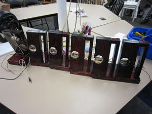
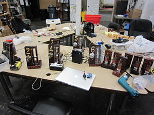
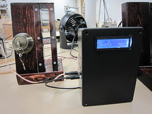
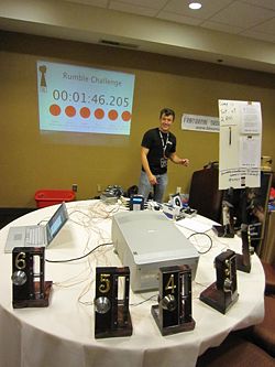
Here at the Fraternal Order Of Lock Sport we take both our sport and our drinking very seriously. For DerbyCon this year we decided we wanted to encourage both as much as possible, so with that in mind we built the Rumble Challenge. It's a lock picking game where 6 people compete head-to-head for the best time each round. Each lock stand has a sensor which allows the microcontroller (ATMega328) to detect and score the players times. Each lock stand has a rumble motor attached which randomly goes off. Why? It's hilarious to see everyone jump when they go off (they are loud), it also throws off the feel of whats happening with the lock.
When the drinking-mode is activated, each time a lock is opened an air-pump triggers which pressurizes a carboy containing the precious liquid to fill each players shot glass. The game stops, each player still in the game gets a shot bonus, then the GO button is pressed to continue. Players who have already opened their locks still get a shot, but no bonus points. Scoring is setup so that getting your lock open first is great, but getting all 6 shot bonuses can potentially put you in first place too.
[edit] Hardware
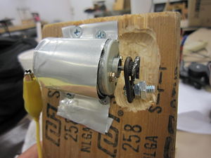
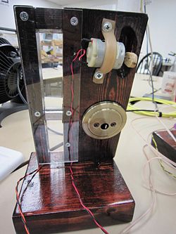
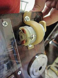
First I mocked-up a vibration motor to a lock stand to see if it would be enough to actually interfere with picking. The first tests were very promising, so I went ahead and geared the project up to full speed.
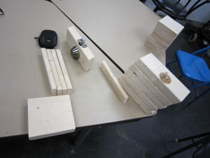
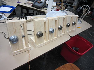
Where the bolt slides out and contacts the 1"x2" plank is a small lever switch embedded into the wood. I used hot glue to embed the switches into the plank, a hole is drilled to the rear where the wires are ran. I carved a channel down the plank to hide the wires under the plexiglass which will be added soon to cover the area around the bolt.
[edit] Drinking Game Mode
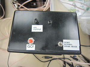
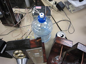
Another motivation for building this was to have a nice drinking game; a switch on top selects one of three modes including drinking mode. I incorporated a formerly-battery powered aquarium pump into the case for dispensing liquids. It was intended to be powered by 1.5V, I run it at 5V via a 7805 regulator and a huge heat sink. The air is pumped into a sealed carboy which contains the liquid, a copper pipe transfers liquid pumped out of the carboy into a manifold and on to the shot glasses. Of course our locksport group already has logo'ed shot glasses so this was a natural extension to the system.
The drinking game mode works like this: Each time a lock is picked open all players get a shot. Each shot consumed by players still in the game gets a shot bonus (including the person who caused the shot to be dispensed). When the shot is dispensed the clock stops and all players must remove their pick from the lock - tensioners may stay in the lock. Shots are consumed, and then the GO! button is pressed on the box to resume the clock. The shot bonus scoring is setup so that the last person to get their lock open has a chance to get the best score since they can potentially get all 6 shot bonuses. Players who have already opened their locks will still get shots dispensed, but no points are awarded for consumption.
[edit] Electronics
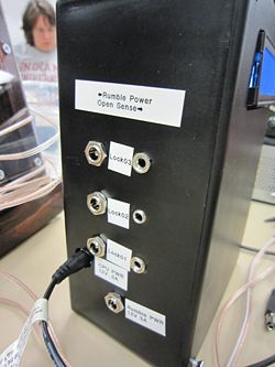
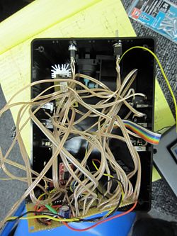
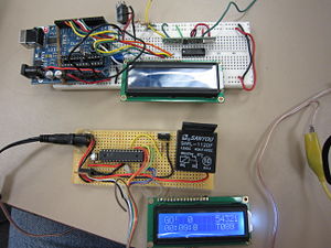
I used an Arduino to prototype the circuit. It's so simple to get an ATMega running on perfboard that I don't waste real Arduino's in my final circuits, just put a socket in there and swap chips when you are done with the code. It transmits lock open-events to a receiver (connected to a PC connected to a projector) as well as dispenses shots in drinking-game-mode :-). The controller has an LCD display so it could operate stand-alone, however I'm more interested in using some cheap RF boards to transmit events to the projector system. I was able to get the code written while I was waiting for parts to ship from SparkFun and Jameco. While the RF system worked great at first, it seems that the motors were causing some occaisonal interference so for the final design I added an FTDI header and used a SparkFun FTDI breakout board for USB connectivity. It's a simple code change to switch from RF to Serial output for communication with the Processing app. For the RF receiver I just used an Arduino+SparkFun proto-shield and receiver board, I didn't have time to build a permanent circuit which was just as well.
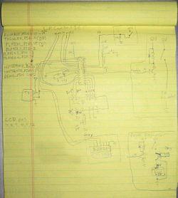
This schematic is merely a suggestion, the only reason I used various pins was because they were free. There are probably a lot of ways to do this better, this is just the way I built it. Some gotchas, the Arduino pins have to be translated to ATMega328 pins, that's usually documented below. The air-pump should run at 1.5V but I'm running it at 5V. You will need a large heat-sink on your power regulator if you do this. I tested the motor before going with this setup, it draws between 300mA and 400mA at 5V which is well within the regulators 1A max. Also, you may enjoy adding things like a reset switch to the microcontroller.
[edit] Debugging
One major problem I ran into with this system is noise from the electric motors causing spurious CPU corruption and lockups. This was a head scratcher for a long time but the answer turned out to be simple in the end. First I isolated the motors to have their own power supply independent from the CPU power supply. This didn't do much, but then I realized I had connected the grounds between the CPU and motor power. I cut these apart on the PCB so the grounds were completely isolated. This helped a lot however it would still lock up often enough to cause major headaches. Also running the air pump/shot dispenser would still lock up the CPU about 80% of the time. Finally a friend suggested putting capacitors on the motors. There are multiple ways to do this, I added two 105 caps to each motor, one cap going from each power lead to the motor case. I also did this on the air pump motor along with a cap across the power leads (in parallel to the motor) since this motor was the worst offender. This solved all of the corruption and lockup problems, the system is 100% reliable now.
Also, for drinking mode, I need to do some work on the "liquid delivery system" by adding fish-tank ball-values on each output tube. Getting even flow of liquid to each shot glass is difficult with the tubing spralled out across a table, differences in tube length, and differences in height. The biggest problem is over-filling shot glasses and having to stop delivery to stations which are missing a player for a round.
[edit] Visualisation
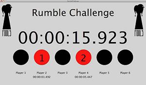
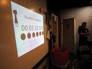
The last component of Rumble Challenge is something to make a nice visualization of how the contest is progressing on the projector. The receiver will feed raw data to a tty on the PC, an application written in Processing will make for a simple visualization system on a projector. Fellow Bloominglabs member Steve wrote up a very nice app which does just this for the project.
[edit] Code
Email me if you are interested in code (dosman [at] bloominglabs [dot] org).
[edit] Action Shots
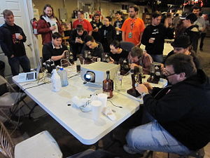
The first run of the game was during DerbyCon 2011 at LVL1's party. We setup the system in full drinking-game-mode with Malibu Rum as the potion of choice. Many thanks for the awesome folks at LVL1 for letting us run the game at their space (hotel rules prohibited drinking in the lock picking village at DerbyCon).
On Saturday we ran the Rumble Challenge in non-drinking mode to satisfy hotel requirements, lots of fun was still had:
