Difference between revisions of "Lockpicking contest system"
| Line 24: | Line 24: | ||
== Electronics == | == Electronics == | ||
| − | I used an Arduino to prototype the circuit. It's so simple to get an ATMega running on perfboard that I don't waste real Arduino's in my final circuits, just put a socket in there and swap chips when you are done with the code. It's main duty is to 1) verify all the locks are connected correctly at power up and 2) transmit lock open-events to a receiver (connected to a PC connected to a projector). The controller has an LCD display so it could operate stand-alone, however I'm more interested in using some cheap | + | I used an Arduino to prototype the circuit. It's so simple to get an ATMega running on perfboard that I don't waste real Arduino's in my final circuits, just put a socket in there and swap chips when you are done with the code. It's main duty is to 1) verify all the locks are connected correctly at power up and 2) transmit lock open-events to a receiver (connected to a PC connected to a projector). The controller has an LCD display so it could operate stand-alone, however I'm more interested in using some cheap RF boards to transmit events to the projector system. I was able to get the code written while I was waiting for parts to ship from SparkFun and Jameco. I'm sure I'll have more debugging to do though once I get the final hardware built. |
A receiver is also needed for the PC. Another Arduino with an RF receiver connected to the PC via USB will finish out the hardware side of things. | A receiver is also needed for the PC. Another Arduino with an RF receiver connected to the PC via USB will finish out the hardware side of things. | ||
| Line 35: | Line 35: | ||
== Visualisation == | == Visualisation == | ||
| − | The | + | The last component of Rumble Challenge is something to make a nice visualization of how the contest is progressing on the projector. The receiver will feed raw data to a tty on the PC, an application written in Processing will make for a simple visualization system on a projector. Fellow Bloominglabs member Steve wrote up a very nice app which does just this for the project. |
| − | + | [[Image:Rr_screenshot01.jpg|none|thumb|300px|Rumble Challenge display - Processing]] | |
Revision as of 10:13, 26 September 2011
Note: please do not link this page anywhere until after DerbyCon1 has finished - thanks!
Contents |
Rumble Challenge Lock Picking Contest System
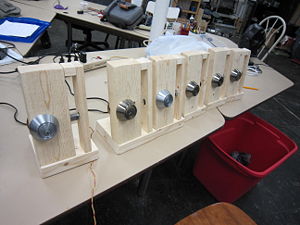
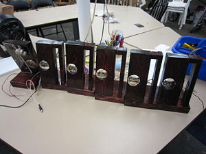
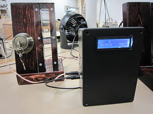
I wanted to build a decent contesting rig for a lock picking village a couple of us are hosting at DerbyCon in September 2011. I've seen the rig the TOOOL folks inherited and use for Defcon, it's very nice but starting to get dated. Firstly, I wanted to come up with something new to jam up pickers during the contest. For this contest I wanted to add a "vibration obstacle" to the challenge. Six contestants compete head-to-head on deadbolt's mounted on lock stands. Each lock stand has a vibration motor attached to the back which is activated intermittently throughout the contest. Second, I wanted a larger presence for the contest- namely a much larger display for what's going on. Lock picking is like hacking in that the actual nut and bolts is rather boring to watch, despite what they show in the movies. The control unit will be based on an Arduino and transmits data to a receiver+laptop connected to a projector. The projector will show the clock and players who have opened their locks so far (along with their individual times). I wanted to build a huge 7-segment timer display, but the cost was too high and I didn't have time to complete that, so a projector will make things "large" and potentially more interesting.
Hardware
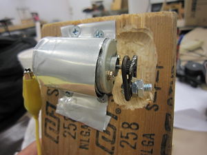
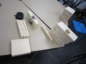
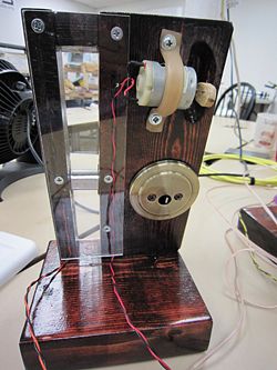
Pics or it didn't happen! First I mocked-up a vibration motor to a lock stand to see if it would be enough to actually interfere with picking. The first tests were very promising, so I went ahead and geared the project up to full speed.
Where the bolt slides out and contacts the 1"x2" plank is a small lever switch embedded into the wood. I used hot glue to embed the switches into the plank, a hole is drilled to the rear where the wires are ran. I carved a channel down the plank to hide the wires under the plexiglass which will be added soon to cover the area around the bolt.
Electronics
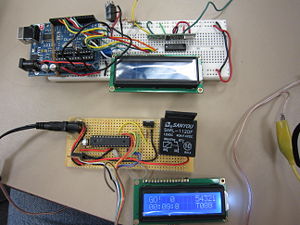
I used an Arduino to prototype the circuit. It's so simple to get an ATMega running on perfboard that I don't waste real Arduino's in my final circuits, just put a socket in there and swap chips when you are done with the code. It's main duty is to 1) verify all the locks are connected correctly at power up and 2) transmit lock open-events to a receiver (connected to a PC connected to a projector). The controller has an LCD display so it could operate stand-alone, however I'm more interested in using some cheap RF boards to transmit events to the projector system. I was able to get the code written while I was waiting for parts to ship from SparkFun and Jameco. I'm sure I'll have more debugging to do though once I get the final hardware built.
A receiver is also needed for the PC. Another Arduino with an RF receiver connected to the PC via USB will finish out the hardware side of things.
Visualisation
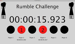
The last component of Rumble Challenge is something to make a nice visualization of how the contest is progressing on the projector. The receiver will feed raw data to a tty on the PC, an application written in Processing will make for a simple visualization system on a projector. Fellow Bloominglabs member Steve wrote up a very nice app which does just this for the project.

